

How Is Axonometric Drawing Used For
Axonometric projection is a type of orthographic projection used for creating a pictorial drawing of an object, where the object is rotated around one or more of its axes to reveal multiple sides.[1]
Overview [edit]
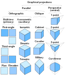
Classification of Axonometric project and some 3D projections
"Axonometry" means "to measure along the axes". In High german literature, axonometry is based on Pohlke'south theorem, such that the scope of axonometric project could cover every blazon of parallel projection, including non only orthographic projection (and multiview project), just also oblique projection. All the same, outside of German language literature, the term "axonometric" is sometimes used just to distinguish between orthographic views where the principal axes of an object are non orthogonal to the project plane, and orthographic views in which the principal axes of the object are orthogonal to the project aeroplane. (In multiview projection these would be called auxiliary views and master views, respectively.) Confusingly, the term "orthographic project" is besides sometimes reserved but for the main views.
Thus, in German literature, "axonometric projection" might exist considered synonymous with "parallel projection", overall; but in English literature, an "axonometric projection" might be considered synonymous with an "auxiliary view" (versus a "primary view") in an "multiview orthographic projection".
With an axonometric projection, the calibration of an object does not depend on its location (i.e., an object in the "foreground" has the same scale every bit an object in the "background"); consequently, such pictures look distorted, as man vision and photography employ perspective projection, in which the perceived scale of an object depends on its distance and location from the viewer. This distortion, the direct result of a presence or absence of foreshortening, is especially evident if the object is mostly composed of rectangular features. Despite this limitation, axonometric project can be useful for purposes of analogy, especially because it allows for simultaneously relaying precise measurements.
3 types [edit]

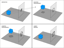
Various projections and how they are produced

The three axonometric views. The percentages show the amount of foreshortening.
The iii types of axonometric projection are isometric project, dimetric projection, and trimetric projection, depending on the verbal angle at which the view deviates from the orthogonal.[2] [three] Typically in axonometric cartoon, as in other types of pictorials, one centrality of space is shown to exist vertical.
In isometric projection, the virtually unremarkably used form of axonometric projection in engineering drawing,[4] the direction of viewing is such that the iii axes of infinite appear as foreshortened, and at that place is a mutual bending of 120° between them. As the distortion acquired past foreshortening is uniform, the proportionality between lengths is preserved, and the axes share a common scale; this eases ane's ability to take measurements directly from the drawing. Some other reward is that 120° angles are easily constructed using merely a compass and straightedge.
In dimetric projection, the direction of viewing is such that 2 of the three axes of infinite appear equally foreshortened, of which the attendant scale and angles of presentation are adamant according to the angle of viewing; the calibration of the 3rd direction is adamant separately. Dimensional approximations are common in dimetric drawings.[ clarification needed ]
In trimetric projection, the management of viewing is such that all of the three axes of space appear unequally foreshortened. The scale along each of the three axes and the angles among them are adamant separately as dictated by the bending of viewing. Dimensional approximations in trimetric drawings are common,[ clarification needed ] and trimetric perspective is seldom used in technical drawings.[iii]
History [edit]
Axonometry originated in People's republic of china.[5] Its role in Chinese fine art was unlike the linear perspective in European fine art since its perspective was non objective, or looking from the outside. Instead, its patterns used parallel projections inside the painting that immune the viewer to consider both the space and the ongoing progression of time in i curlicue.[6] According to scientific discipline author and Medium journalist Jan Krikke, axonometry, and the pictorial grammar that goes with it, had taken on a new significance with the introduction of visual computing and engineering drawing.[6] [5] [7] [8]
The concept of isometry had existed in a rough empirical form for centuries, well before Professor William Farish (1759–1837) of Cambridge Academy was the first to provide detailed rules for isometric cartoon.[nine] [ten]
Farish published his ideas in the 1822 paper "On Isometric Perspective", in which he recognized the "need for accurate technical working drawings free of optical distortion. This would lead him to formulate isometry. Isometry means "equal measures" considering the same scale is used for height, width, and depth".[11]
From the centre of the 19th century, according to January Krikke (2006)[11] isometry became an "invaluable tool for engineers, and shortly thereafter axonometry and isometry were incorporated in the curriculum of architectural training courses in Europe and the U.S. The popular acceptance of axonometry came in the 1920s, when modernist architects from the Bauhaus and De Stijl embraced information technology".[11] De Stijl architects like Theo van Doesburg used axonometry for their architectural designs, which caused a sensation when exhibited in Paris in 1923".[11]
Since the 1920s axonometry, or parallel perspective, has provided an important graphic technique for artists, architects, and engineers. Similar linear perspective, axonometry helps describe 3-dimensional space on a ii-dimensional picture airplane. It usually comes as a standard characteristic of CAD systems and other visual computing tools.[six]
-

Optical-grinding engine model (1822), drawn in 30° isometric perspective[12]
-
Example of a dimetric perspective drawing from a U.s.a. Patent (1874)
-

Detail of the original version of Forth the River During the Qingming Festival attributed to Zhang Zeduan (1085–1145). Notation that the flick switches back and forth between axonometric and perspective projection in unlike parts of the image, and is thus inconsistent.
Limitations [edit]

In this cartoon, the bluish sphere is two units higher than the cerise one. Withal, this difference in elevation is non apparent if one covers the right half of the picture.

The Penrose stairs depicts a staircase which seems to ascend (anticlockwise) or descend (clockwise) yet forms a continuous loop.
As with other types of parallel projection, objects drawn with axonometric project exercise not appear larger or smaller equally they lie closer to or farther away from the viewer. While advantageous for architectural drawings, where measurements must be taken directly from the image, the result is a perceived distortion, since different perspective projection, this is not how human vision or photography normally works. Information technology too can easily effect in situations where depth and altitude are difficult to approximate, as is shown in the analogy to the right.
This visual ambiguity has been exploited in op art, as well as "impossible object" drawings. Though not strictly axonometric, Thousand. C. Escher's Waterfall (1961) is a well-known paradigm, in which a aqueduct of h2o seems to travel unaided forth a downwardly path, only to so paradoxically fall once again every bit it returns to its source. The water thus appears to disobey the law of conservation of free energy.
References [edit]
- ^ Gary R. Bertoline et al. (2002) Technical Graphics Communication. McGraw–Hill Professional, 2002. ISBN 0-07-365598-8, p. 330.
- ^ Maynard, Patric (2005). Drawing distinctions: the varieties of graphic expression. Cornell University Press. p. 22. ISBN0-8014-7280-6.
- ^ a b McReynolds, Tom; David Blythe (2005). Advanced graphics programming using openGL. Elsevier. p. 502. ISBNane-55860-659-9.
- ^ Godse, A. P. (1984). Computer graphics. Technical Publications. p. 29. ISBN81-8431-558-ix.
- ^ a b Krikke, Jan (2018-01-02). "Why the earth relies on a Chinese "perspective"".
- ^ a b c Jan Krikke (2000). "Axonometry: a matter of perspective". In: Computer Graphics and Applications, IEEE Jul/Aug 2000. Vol 20 (iv), pp. 7–11.
- ^ "Axonometry: A Matter of Perspective". July 2000.
- ^ "A Chinese Perspective for Cyberspace".
- ^ Barclay G. Jones (1986). Protecting historic architecture and museum collections from natural disasters. Academy of Michigan. ISBN 0-409-90035-iv. p. 243.
- ^ Charles Edmund Moorhouse (1974). Visual messages: graphic communication for senior students.
- ^ a b c d J. Krikke (1996). "A Chinese perspective for internet? Archived 2009-06-01 at the Wayback Machine". In: International Institute for Asian Studies Newsletter, nine, Summer 1996.
- ^ William Farish (1822) "On Isometrical Perspective". In: Cambridge Philosophical Transactions. 1 (1822).
- Technical drawings — Projection methods — Part 3: Axonometric representations, ISO 5456, International Organization for Standardization, 1996-06-15, ISO 5456-3:1996(en)
Further reading [edit]
- Yve-Alain Bois, "Metamorphosis of Axonometry," Daidalos, no. 1 (1981), pp. 41–58

Source: https://en.wikipedia.org/wiki/Axonometric_projection
Posted by: powellagar1989.blogspot.com
0 Response to "How Is Axonometric Drawing Used For"
Post a Comment